Repowering
Fuel Hookup
At first the plan was to run a new rubber hose from the Racor filter to the engine. This simple concept turned into the most difficult part of the project. While reading the installation manual for the engine I learned that a fuel return line was needed. I also realized the fuel supply needed some improvements. I'll discuss the fuel return issue first.
The Fuel Return
A fuel return is necessary for a diesel engine since not all of the fuel supplied by the injection pump gets into the cylinder. Some of it is to be returned back to the tank for later use. I looked at tying the return into the supply line with a tee. The problem is that the return fuel is quite warm and would cause problems. Also this engine has a self bleeding feature that would be defeated if the return were teed into the supply because it would simply circulate the air bubbles.
There are some regulating organizations that concern themselves with boat construction. The Code of Federal Regulations 33 CFR 158.518 found at GPO Access requires openings to be in the top. The ABYC is silent on the issue so some folks infer that it is ok. I decided that the chance of a slow leak or seapage was too great. If there was a fire the rubber gasket would melt and allow diesel to leak. I decided to put it in the top. I also needed something to go on if there ever was a problem that led to an insurance claim.
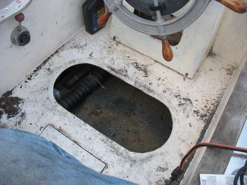
I have investigated adding an inspection port over the last several years. I realized that I would need to build a hatch in the cockpit in order to install it and access it properly. The following details the construction of the access hatch.
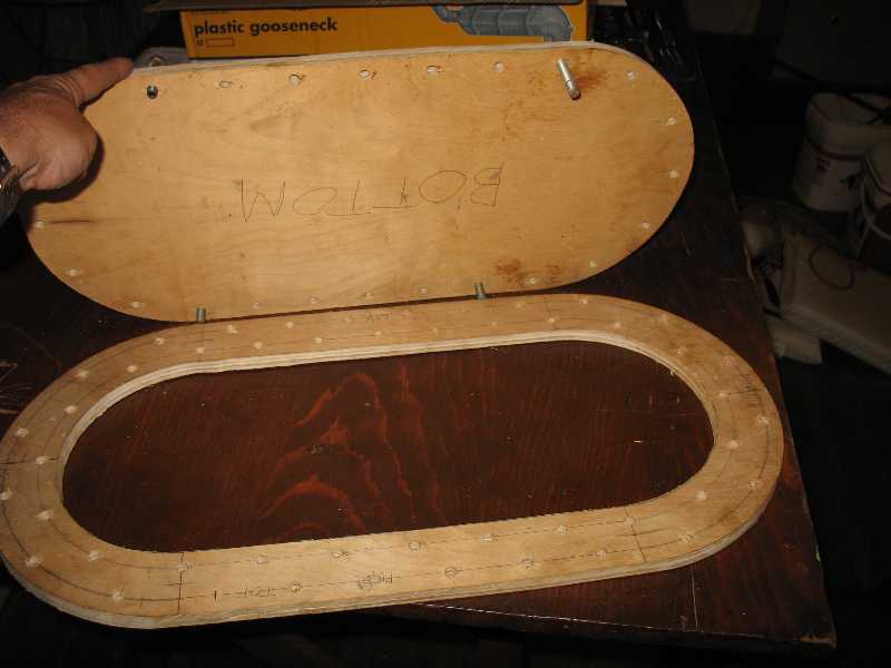
Again I make a wooden prototype pattern. The hatch consists of a frame and lid. The hatch needed to be flush with the cockpit deck. Wood works well for this type of template as it allows me to position the holes with good precision. Also I can make design decisions cheaply with the template.
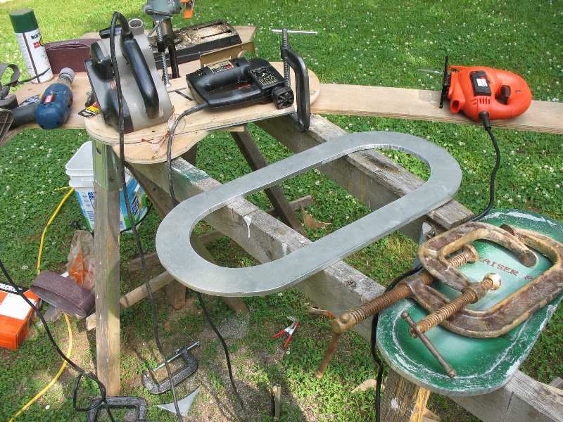
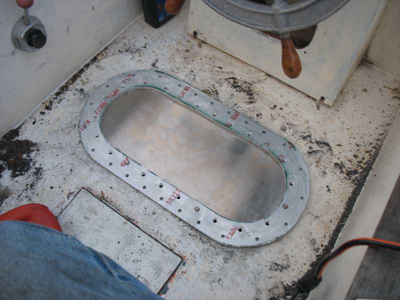
I went to Online Metals and orderd 6061 T aluminum plate. This is quite strong but light weight and should resist corrosion. Also it is relatively easy to cut and drill. Then all I have to do is duplicate the template in the aluminum. Shown here is the frame cut from 3/8" plate for strength and stiffness and smoothed with a belt sander..
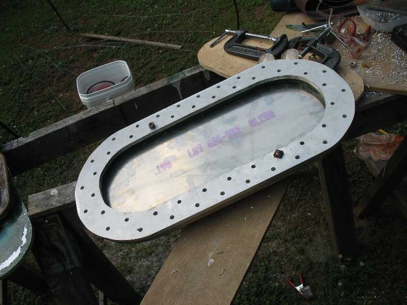
Shown here is the completed hatch. I used the frame template to establish the holes in the frame and the lid. I then tapped the holes in the frame for 3/8" x 16 phillips flat head screws. I chamfored the holes in the lid to accomodate them and leave a flat surface.
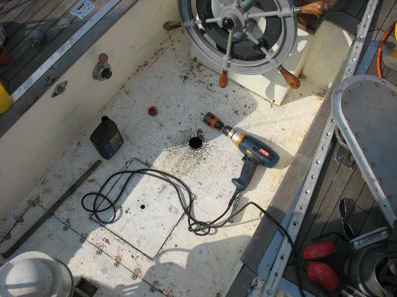
I always get an awful feeling about cutting a hole in any part of the boat, especially steel. I cut this small hole in the cockpit so I could verify my measurements for placement of the hatch.
I used the hatch lid to mark the hole. I had to make sure the lid matched the hole as it is not a perfect oval. It took about 2 arduous hours with the saber saw to cut the hole.
I used the hatch frame as a template and guide to drill the mount holes. I put the lid on the bottom of the frame to position it. I then drilled the first two holes. I then took the lid off and bolted the frame down so it would not move at all. I then drilled the remaining holes. I had to be very careful to get the lid and frame on right for this step or I'd wind up with mismatched holes or a lid that did not quite match.
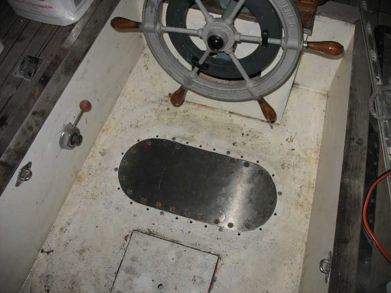
Here the hatch installation is nearly finished. As it is not quite perfect, the hatch fits in only one way. The holes match perfectly as required. I will rarely need to open this. If I do there is a bit of a gap at the bottom right in the picture to use for prying up the lid with a screw driver. I finished by gluing the lid in with 3M 5200 and then installing 1/4" bolts. The holes are 5/16" which allows for thermal expansion as the coefficent of thermal expansion of aluminum is nearly twice that of steel. I used Ospho, Evaporust, and Zinga on the raw edge of the steel. I sprayed everything with green Rustoleum to protect the raw edge of the steel. I will later paint it white.
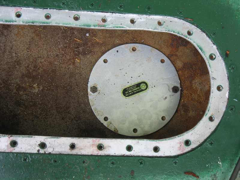
I bought an 8" Seabuilt fuel tank access plate made by www.seabuilt.com. Before positioning it I tapped on the tank to locate baffles. I determined that there was a center baffle for sure. I thought there might be a cross baffle. I quickly improvised a plan to deal with that. Once I drilled a hole in the tank I was committed to finishing this.
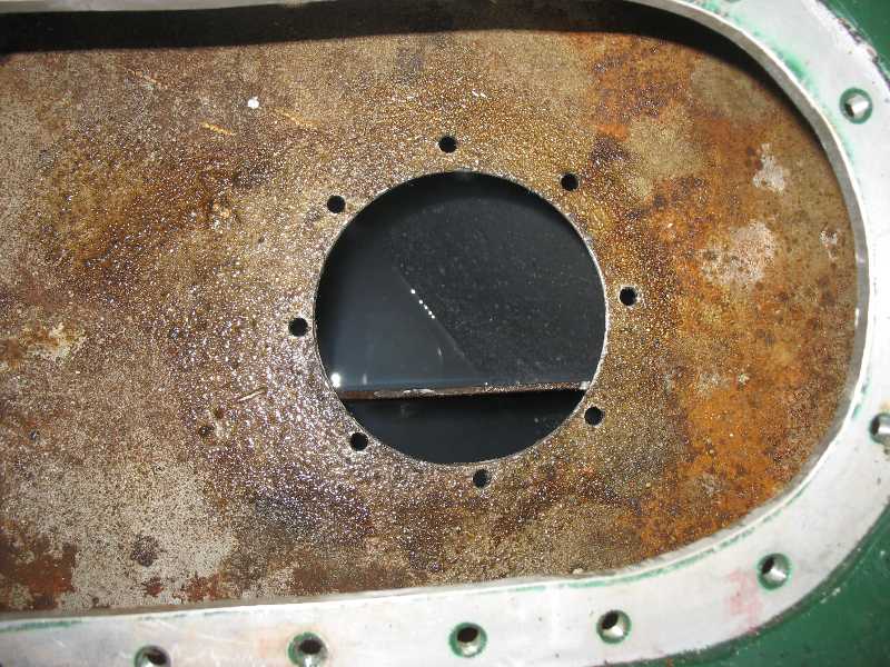 I drilled the 8 holes and then got the hole saw out to cut the hole. It was not too
diificult. However I pushed the drill to the limit. It got quite hot and even started smoking. I stopped and let it cool
down before continuing. The bolt holes are closer to the edge of the hole than I like. So next time I'll use a 5 3/4 or 5 1/2
hole saw instead of the 6". As you can see there is a baffle. If I had the tools I would have removed the top 1/2 inch of
it on the right for a distance one inch inside the hole to one inch under. Even if I got the baffle cut I would have to smooth
the spot where it was welded on. It would be difficult to get it smooth enough for the rubber gasket to work. I have learned to
eschew modifying a product installation such as this but I really had no choice here. I ended up cutting a small portion off of
one of the C shaped backing pieces in order to fit around the baffle. I put the
rubber gasket ring only on the outside. Since the top of the fuel tank was a bit rough I used RectorSeal #5. I put the rubbber
gasket on and then the plate and tightened the bolts.
I drilled the 8 holes and then got the hole saw out to cut the hole. It was not too
diificult. However I pushed the drill to the limit. It got quite hot and even started smoking. I stopped and let it cool
down before continuing. The bolt holes are closer to the edge of the hole than I like. So next time I'll use a 5 3/4 or 5 1/2
hole saw instead of the 6". As you can see there is a baffle. If I had the tools I would have removed the top 1/2 inch of
it on the right for a distance one inch inside the hole to one inch under. Even if I got the baffle cut I would have to smooth
the spot where it was welded on. It would be difficult to get it smooth enough for the rubber gasket to work. I have learned to
eschew modifying a product installation such as this but I really had no choice here. I ended up cutting a small portion off of
one of the C shaped backing pieces in order to fit around the baffle. I put the
rubber gasket ring only on the outside. Since the top of the fuel tank was a bit rough I used RectorSeal #5. I put the rubbber
gasket on and then the plate and tightened the bolts.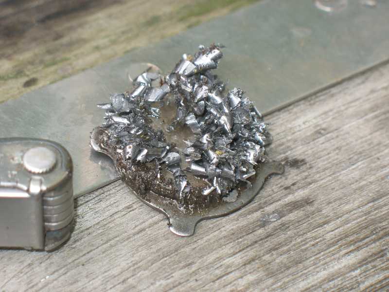
This magnet makes a fine way to clean up metal chips from drilling and cutting.
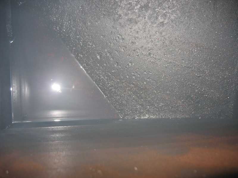 The inside of the diesel tank looks to be in pretty good shape. It's angular shape helps
the fuel to slosh around and coat the entire inside and keep it from rusting as long as I use the boat regularly.
The inside of the diesel tank looks to be in pretty good shape. It's angular shape helps
the fuel to slosh around and coat the entire inside and keep it from rusting as long as I use the boat regularly.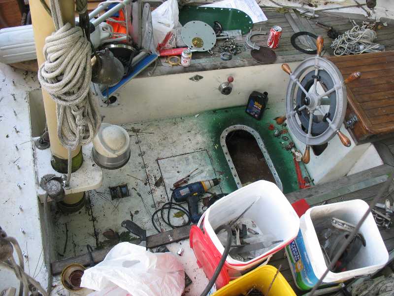 Here is the work site with all the tools I am using today. With the boat next to
trees it is hard to keep it clean. Parts of the Seabuilt plate are visible at the top.
Here is the work site with all the tools I am using today. With the boat next to
trees it is hard to keep it clean. Parts of the Seabuilt plate are visible at the top.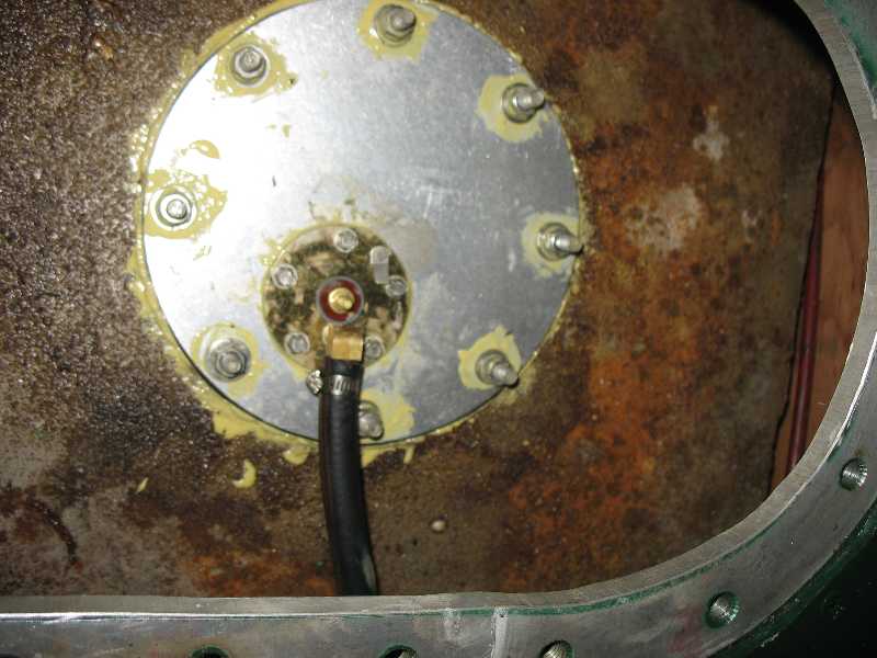
The fuel return is completed. The return hose extends into the compartment. I had purchased a combination fuel return and fuel level indicator. Because of the way the tank is baffled I could not determine an easy way to mount it and through bolt it. Also this unit worked with a float that swung out from the center. I then noticed that the bolts that came with the unit were very short. Also there was only one nut supplied. I realized that it was meant to be mounted in holes that were drilled and tapped. I had talked to David A earlier and he said that it wasn't kosher to screw something like this into 1/8" thick metal since there is not enough metal to get good threading into. Also baffles prevented access to the other parts of the tank to through bolt it. That left the access plate. I again used RectorSeal #5. I used 5200 for the nuts to keep them from falling off into the fuel tank later. I bolted the plate down and tightened up good. Then I connected the fuel hose.
The Fuel Supply
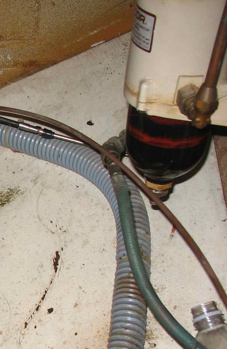
The Racor filter had a galvanized pipe coming out the back. I'm told that diesel fuel reacts with the zinc in the galvanizing and eventually corrodes the pipe. I removed it and put a 1/4 npt brass fitting in for the supply fuel hose.
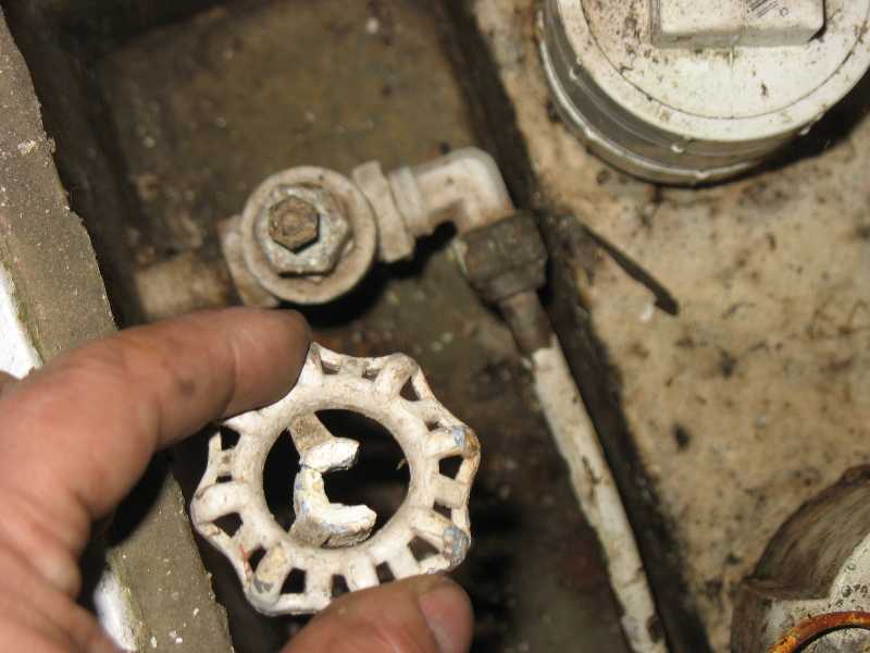
This was a gate valve with a rusted handle. It broke when I asked Jeff C to close the fuel supply line just before I unhooked the engine.
I changed it to a proper globe valve. I can tell at a glance whether it is open or shut. I had to make the handle shorter though. I pulled off the plastic. Then I cut and rounded the handle. I cut the plastic shorter and slipped it back on so the valve looked like it was made that way.
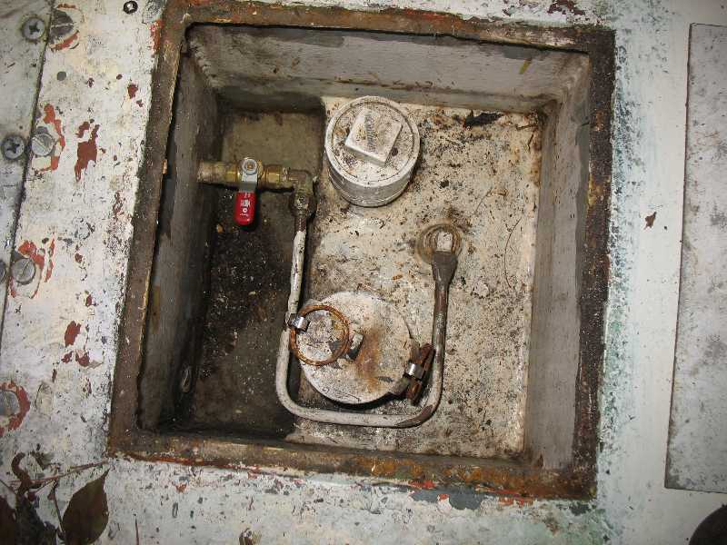
Now everything is done. All I have to do is hook up a fuel and return hose when I set the engine in place.